
This work is licensed under a Creative Commons Attribution-Noncommercial-No Derivative Works 2.5 License.
This work is licensed under a Creative Commons Attribution-Noncommercial-No Derivative Works 2.5 License.
 Download a Russian translation (PDF) by Konstantin Kornienko (kkonstantini@mail.ru)
Stations
Movements with Railway Vehicles
Classification of Tracks
Operating Staff
Block Working without a Line Block
System
Manual Block Working
Automatic Block Working
Locking Frames
Facing Point Locks
Route Locking
Station Block System
Overlaps
Flank Protection
In the English speaking world, excellent textbooks are available on railway signalling. Some of them concentrate either on the British or on the North American principles while other books compare the two philosophies. However, in all these books, the German block and interlocking principles are almost completely ignored. This is not surprising and has two obvious reasons. The first reason is the language. Information on German block and interlocking systems is hardly available in any other language than German. The second reason is that, for people that grew up in the English-speaking railway world, the German systems often seem odd and difficult to understand. A very typical example is the role of the German block instrument, the so-called "Blockfeld", which is an essential element of traditional German block and interlocking systems but has no equivalent in the English-speaking railway world. Since Germany has the biggest national railway network in Europe (more than 35,000 km) that easily doubles the British network, and the German principles have been adopted by many countries outside Germany and the German-speaking countries (e.g. entire Eastern Europe, Scandinavia, the Balkan countries, countries in the Middle East), some basic information on the German principles might be interesting for Non-German readers. This is the purpose of the following chapters. The article excludes the subject of signal aspects since excellent material on German signal aspects is available in English at www.sh1.org/eisenbahn/index.htm.
The explanations mainly concentrate on traditional block and interlocking systems developed in the steam era. The reason for this is not nostalgia. It is simply easier to understand the fundamental principles from the traditional systems. Most of these principles survived until today and can still be found in the latest computer-based control systems. Having understood the old systems makes it quite easy to understand any technology developed later. On the other hand, without knowledge on the historical development, many principles that can be found in modern control systems seem odd or difficult to understand.
To understand block and interlocking systems, some information on basic terms of German railway operation is absolutely necessary. Otherwise, misunderstandings will occur almost automatically.
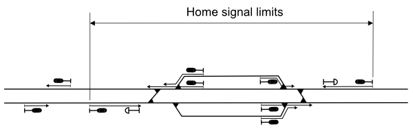
Like on most railways outside North America, there is a strong distinction between station tracks and tracks of the open line. This distinction has many influences on operating rules and on signalling principles as well. However, real station tracks only exist in a specific kind of station which is called a "Bahnhof". There is no suitable word to translate this term into the English language. A "Bahnhof" is a track arrangement limited by opposing home signals, with at least one turnout, where trains may originate, terminate, pass, overtake, and turn. The tracks outside these home signal limits are called the open line. The signals that govern train movements to leave the home signal limits are called exit signals. The role of an exit signal is in some way similar to a British starter signal. However, exit signals are placed before the point zone. With a few exceptions, there is no signal comparable to the British advanced starter signal. As a result, the block section that is limited by the exit signal, laps into the home signal limits.
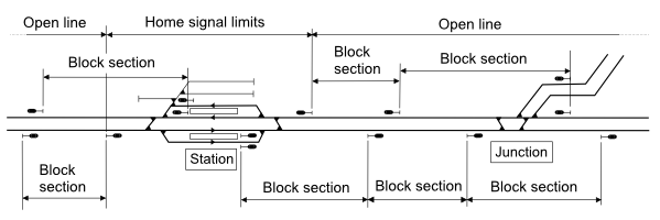
Home signal limits and block sections
In extended home signal limits, there are often intermediate interlocking signals which divide the station track into several section. A train may even have several successive scheduled platform stops without leaving the home signal limits.
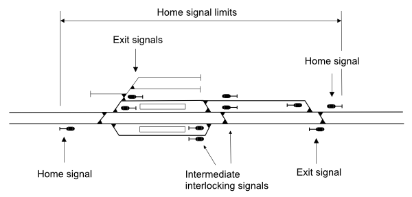
Home signal limits with intermediate interlocking signals
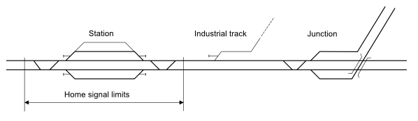
The track sections between main signals inside the home signal limits are not referred to as block sections. Junctions and crossovers outside the home signal limits belong to the open line. The main signals protecting these junctions and crossovers are referred to as block signals but not as home signals. Different from junctions and crossovers inside home signal limits, these junctions and crossovers are called a junction station or a crossover station. Platform stations for passenger trains are not necessarily associated with home signal limits. Platforms can be located both on a station track and on a track of the open line.
Most railways outside North America have a clear distinction between two or three classes of movements with railway vehicles. In Germany, there is a distinction beween two kinds of movements:
Train movements (in some way an equivalent to the British running movements, but not exactly) are all movements that leave the home signal limits and all movements within the home signal limits that are made by the working timetable. Beside a timetable, to enter a section of track, a train movement needs a movement authority from the train director (see chapter on operating staff). Depending on the signalling system, the movement authority is given by:
Speed and brake conditions of train movements are given in the working timetable. Trains always display rear end markers.
Shunting movements are all movements other than train movements. On tracks controlled by a signalbox, a shunting movement needs a movement authority from the point operator (see chapter on operating staff). The movement authority is given by:
A main signal is never cleared for a shunting movement. Shunting movements do not have a working timetable. Instead, employees involved in the movement are verbally informed. Shunting movements run by sight at a maximum speed of 25 km/h. They do not display rear end markers.
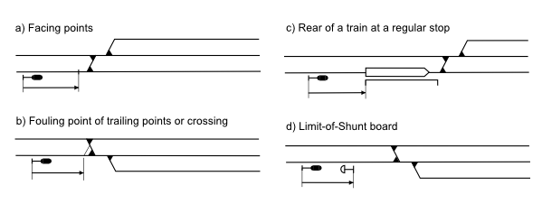
If a shunting movement is going to enter a main track (see chapter on tracks), the point operator has to obtain permission from the train director. Shunting movements must never leave the home signal limits. However, on a double-track line, the departure track (i.g. the right track) may be used by shunting movements by the length required to move vehicles from one station track to another. If a train is approaching the station on that track, the train director has to set a temporary shunting limit at a location specified in local rules. The shunting limit on the arrival track (i.e. the left track) is marked by a Limit-of-Shunt (LOS) board. The LOS board is placed at the overlap distance beyond the home signal. At stations without LOS boards, the arrival points (i.e. the points of the first turnout met by an arriving train) are the shunting limit.
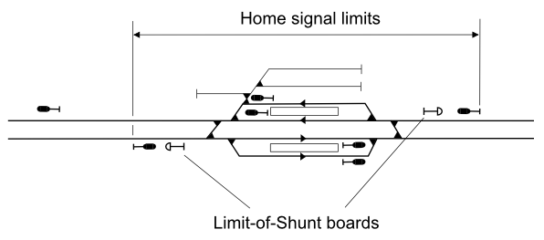
Limit-of-Shunt boards
To shunt beyond the LOS board or, if not used, the arrival points, a written permission from the train director is necessary. Before issuing the permission, the train director has to ensure that no train is approaching the home signal on that track. If the signal in rear of the home signal is not in the control district of the train director, the train director must obtain confirmation of the adjacent train director that trains will be held back.
At places where an industrial track is connected to the open line, the movements to enter and to leave the industrial track are shunting movements. However, the movements between that place and the next station are always train movements. Since shunting movements must not leave the home signal limits, home signals are not equipped with a shunt aspect. It is not possible to start a shunting movement at the home signal. A train that should be shunted must have arrived at the station track.
In railway operation, there is a distinction between two classes of tracks:
Main tracks are the German equivalent to the British running lines. These are all tracks that may be regularly used by train movements. Main tracks must be equipped with signal installations required for train movements. Secondary tracks are all tracks other than main tracks. Normally, secondary tracks are only used for shunting movements. However, in exceptional situations under specific safety precautions, trains may be authorised to use a secondary track.
In contrast to the British signallers, in German signal boxes there are two ranks of operating staff that even result in two classes of signal boxes:
The train director is the authority person for controlling all train movements. The German term "Fahrdienst" (a literal translation would be "running service") is an obsolete term in contemporary German railway operation that only survived for traditional reasons in that job title. The working place of the train director is usually a signal box. But the control district of a train director may be much greater and it may contain several signal boxes, usually all signal boxes inside the home signal limits of a station. Since in Germany, loop tracks are longer than on British railways, in the days of mechanical signal boxes, most stations had more than one signal box within the home signal limits. The signal box where the train director works is called a command box or a train director's box. Signal boxes not staffed with a train director are called dependent boxes. Dependent boxes are staffed with point operators. All signal boxes in the control district of a train director are electrically connected to each other by a so-called station block system which is described in the chapter on interlocking principles. To clear a signal for a train movement in a dependent box, it has to be electrically unlocked by the command box. That way the train director has positive control over all train movements. In Southern and South-Eastern Germany, and in the states of the former Empire of Austria-Hungary (today Austria, the Czech Republik, Slovakia, Slovenia, and Hungary), the train director was often completely relieved from operating points and signals. The working place of the train director was not a signal box but an office in the station building where the train director was also performing the work of a station master. To ensure positive control over all train movements, the train director had a command machine from which the levers of all main signals were kept locked.
Shunting is entirely in charge of the point operators. Every point operator controls the shunting movements in the district of the own signal box. However, before authorising a shunting movement to enter a main track, the point operator has to ask the train director to avoid conflicts with train movements. If the train director operates points in the command box, the train director is also a point operator for the control district of that signal box. Thus, a train director may have a point operator district that is much smaller than the train director district.
In modern centralised control systems, the distinction between command boxes and dependent boxes is obsolete, since the train director controls directly all points and signals within the control district.
On lines without an automatic block system, block stations that do not protect any point are staffed by block operators who operate on their own responsibility. Thus, a block operator is some kind of a little train director, just responsible for two block signals. In contrast to a point operator, a block operator is not a subordinate of a train director.
German railway operation is based on absolute block. Permissive working is only used on mass transit railways that are completely separated from the standard railway network. On almost all lines, train movements are controlled by signals (fixed main signals or cab signals). Non-signal controlled operation can only be found on a very few branches.
A fact that often leads to misunderstandings for Anglo-Saxon readers is the German use of the term line block system (German: Streckenblock). In the German philosophy, having block sections and running trains in absolute block distance does not necessarily mean to have a block system. A block system always means that, after a train has entered a block section, the signal at the entrance of that section is positively locked in stop position until the train has entirely passed the next main signal and is protected by a stop aspect. That means, "to block" always means "to block and lock". From the German point of view, older British block instruments without "block and lock" working are not regarded as real block systems.
Based on this terminology, there are three types of absolute block working:
On lines not equipped with a line block system, train movements on the open line are protected by telephone messages exchanged between local operators, i.g. train directors and block operators of intermediate block stations. This requires to have all stations that limit a block section locally staffed. Before an exit signal that leads onto a single track line is cleared, the train director has to offer the train to the next train director. After that train director accepted the train, it may leave the departure station. After the train has entered the block section, the train director of the departure station gives a departure message to the receiving train director and to all intermediate block stations. After the train has cleared a block section, the train director or block operator checks that the train has cleared the overlap and is displaying a rear end marker. Then, the signal is reset to stop and a block release message is given to the station in rear.
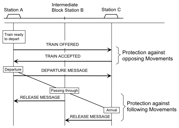
Train messages on a single track line
In train messages, trains must always be clearly identified by their train numbers. To avoid mixing train messages with other telephone conversation, a train message dialogue has always to start with the words "Train message!". Here is an example of typical dialogues (letters A, B, C refer to the picture above):
Train director A calls train director C. Block operator B is listening.
Train director A: "Train message! Do you accept train 52180?"
Train director C: "Train 52180, yes."
Train director A: "I repeat: Train 52180, yes."
Train director C: "This is correct."
Train director A calls train director C. Block operator B is listening.
Train director A: "Train message! Train 52180 left at 12:03."
Train director C: "I repeat: Train 52180 left at 12:03."
Train director A: "This is correct."
Block operator B calls train director A.
Block operator B: "Train message! Train 52180 in B."
Train director A: "I repeat: Train 52180 in B."
Block operator B: "This is correct."
Train director C calls block operator B.
Train director C: "Train message! Train 52180 in C."
Block operator B: "I repeat: Train 52180 in C."
Train director C: "This is correct."
On double track lines, offering and accepting trains is not required. There, trains are just protected by the departure and release messages. After a block release message has been received, a following train may be authorised to enter the block section without asking the next station (open block philosophy). However, double track lines where train movements are just protected by train messages can hardly be found today. They probably vanished completely.
All train messages are manually recorded in a train record. Before clearing a signal for a train to enter a block section, the train director has to check in the train record that the block release message for the last train ahead was received and - on single track lines -, that no train from the opposing has been accepted. A block operator of an intermediate block station has just to check the block release message. Thus, the safety of train movements entirely depends on the accurate handling of the procedure without any positive protection against human errors. That is, why German government regulations allow that form of block working only on lines with a low density of traffic. Today, most of these lines have been converted to non-signalled track warrant operation where a central train director controls train movements directly by exchanging radio messages with train crews. This way, this form of block working has almost vanished today. However, an understanding of that principle is essential for an understanding of the more advanced systems.
In contrast to British block instruments, the German manual block system is not a communication system but a pure safety appliance that adds positive locking of signals to the block working. On manual block lines, with the exception of block release messages, train movements are generally controlled by the same train messages as on lines without a line block system. However, the train messages are no longer a safety procedure but just for traffic regulation. Block release messages are obsolete since block release is safely effected by the line block system.
The development of the German manual block system is closely related to the invention of the characteristic German block instrument, in German called a "Blockfeld" (literal translation: block field). This term sounds completely odd even in the German language. It was named after the instrument's small indicator field. German signalling experts proposed to replace the odd term "Blockfeld" by the much better term "Fernschloss" (remote locking device) but that idea was not successful. So we have still to live with the tradional term. The German block instrument was invented by Carl Frischen in 1871. In German signalling history, Carl Frischen played a very similar role as Edward Tyer in Britain and William Robinson in the USA.
 Carl Frischen (1830 - 1890) |
 Early design of block instruments |
A block instrument looks like an oblong rectangular box, mostly painted green or grey, with a block button on top (often shaped like a small lever) and an indicator window on the front (the "field"). All block instruments of a signal box are usually arranged side by side in a common box. Such an instrument is an electric locking device by means of which the operator can produce a locking (e.g. lock a lever) that cannot be released from the same instrument. The locking produced by a block instrument can only be released from a connected instrument located in another signal box or by the train passing over some contact device. The indicator window shows red colour to indicate the locking of a signal (by this or a connected instrument) and shows white colour to indicate the release of a signal. A block instruments has two positions called "blocked" and "unblocked". The block button can only be pushed if the instrument is unblocked. By pushing the block button, it will change to the blocked position. There are two basic types of block instruments:
With AC block instruments, two instruments located in different signal boxes are connected by a block line. The two instruments are always in opposing positions, i.g. one instrument is blocked while the other is unblocked. The unblocked instrument can be operated by pushing the block button and throwing a block inductor crank at the side of the box. This produces a block current of 12 Hz which is sent to the connected instrument. Receiving the block current unblocks the connected instrument. Now, this instrument can be blocked to restore the original state of the two instruments.
The picture demonstrates the working of connected block instruments. In the upper figure, the instrument in signal box 1 is unblocked, and the instrument in signal box 2 is blocked. The two instruments show a white indicator since no signal is locked. If the instrument in signal box 1 is oerated to the blocked position, it will lock a signal lever and at the same time unblock the instrument in signal box 2. Now, the two instruments show a red indicator (lower figure). The locking of the lever in signal box 1 can now only be released by operating the instrument in signal box 2. Note that the two connected instruments alway show the same colour. The colour of the indicator does not correspond to the position of the block instrument but to the locking effected by the two instruments.
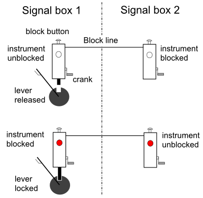
Connected block instruments
DC block instruments work with DC battery power. The are operated just by pushing the button without throwing a crank. A DC instrument has no connected instrument. DC instruments are unblocked by trackside contact devices. A typical contact device used for that purpose is a short track circuit of about 30 m combined with an axle contact. To unblock the instrument, the track circuit must have been occupied and then cleared again, i.g. the train must have completely passed over that circuit. The axle contact is just for additional safety to avoid unblocking the instrument by short interruptions of the track current.
In a line block system, the following block instruments are used:
| Abbr. | German term | Translation | Description |
|---|---|---|---|
| A | Anfangsfeld | Entrance instrument | Operation of this instrument locks the signal at the entrance of a block section in stop position. It is connected to an exit instrument at the exit of the block section. |
| E | Endfeld | Exit instrument | Operation of this instrument releases the locking of the signal at the entrance of the block section. It is connected to an entrance instrument at the entrance of the block section. |
| Erl | Erlaubnisfeld | Opposite locking instrument | Operation of this instrument locks all signals at the entrance of a single track section and releases opposing signal at the other end of that section. It connected to an opposite locking instrument at the other end of the single track section. |
The first figure shows the block equipment of a double track line between two stations with an intermediate block station. Opposite locking is not required since the two tracks have one-way operation. There is an entrance instrument at the entrance of each block section and a connected exit instrument at the exit of each block section. In normal state, all entrance instruments are unblocked while the exit instruments are blocked. Since no signal is locked by the line block system, all instruments show a white indicator. In the left station, exit signal N2 is cleared for an approaching train to enter the block section.
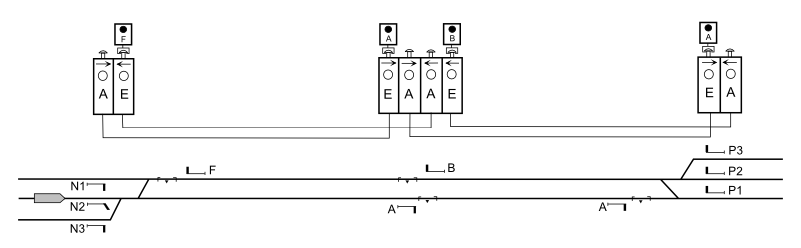
Signal cleared to enter the block section
After the train has departed, the operator resets the signal to stop and operates the entrance block instruments. The signal is now locked by the entrance instrument. The blocked entrance instrument also locks all other exit signals in that station for movements into the same block section. In the figures, signals locked by the block system are marked by red colour of the arm. Operating the entrance instrument will unblock the connected exit instrument at the intermediate block station. Both instruments show now a red indicator meaning the section is now locked for a train movement. After having restored an exit signal or a block signal to stop position, it is automatically locked by a line rotation locking device (German: Streckenwiederholungssperre) until the entrance instrument has been properly operated. This prevents the operator to clear a signal again in case the block instrument failed or the operator forgot to operate it. This way, a train that has entered a block section is always protected against following movements by a signal positively locked in stop position.
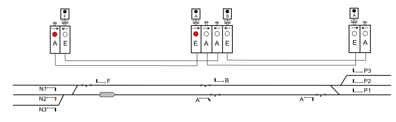
Block section locked
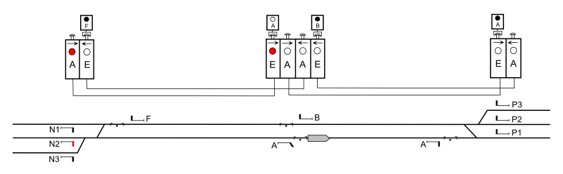
Meanwhile, the block operator at the intermediate block station has cleared the block signal and is expecting the train. At the end of the overlap behind the block signal, there is a short track circuit with an axle contact connected to an electric button lock (German: elektrische Tastensperre) mounted above the exit block instrument.
 Block instruments at an intermediate block station |
From a technical point of view, the electric button lock is just a smaller version of a DC block instrument. Austrian railways even use a full size DC block instrument mounted not above but beside the exit instrument. That DC block instrument is called a button lock instrument (German: Tastensperrfeld, abbrivation: Ts). That is why, different from the arrangement of a German block station as shown in the left photograph, an Austrian block station has not four but six block instruments. |
The electric button lock locks the button of the exit instrument until the train has occupied and cleared again the short track circuit and the train has operated the axle contact. Thus, it is not possible to operate the exit instrument until he train has passed over that track circuit by its entire lenth. However, the operator still has to check train integrity by watching the rear end marker. This provides even a higher degree of safety than the British principle of having a berth circuit before the signal, since it is not possible to release a block section if the train is still somewhere in the middle of the section. The indication window at the electric button lock shows black colour if the button is locked and white colour if the button is released.
Electric button lock released
When operating the exit instrument, the electric button lock automatically switches back to the locking position. To avoid the electric button lock from being released by irregular movements, e.g. movement against the current of traffic or shunting movements into the overlap of a home signal, the track circuit and the axle contact are switched off in normal state and are only activated by clearing the signal. The operator can also manually switch on these devices to keep the block system working for movements that are for some reason authorised to pass the signal in stop position. Beside from the release of the block button by the electric button lock, the signal must have been reset to stop position before it is possible to operate the exit instrument.
Thus, after the train has passed through the intermediate block station, the operator resets the signal to stop position, operates the entrance instrument for the section ahead, and operates the exit instrument for the section in rear. As a result, the section in rear is released, and the section ahead is blocked.
Next section locked, section in rear released
On single track lines, connected opposite locking instruments are installed at the stations limiting a single track section. The blocked opposite locking instrument locks all signals leading into the single track line. This instrument shows a red indicator while the connected instrument shows a white indicator. This is the only example where connected block instruments show different colours.
Block instruments on a single track line
To change the direction, the operator at the station where the opposite locking instrument is unblocked has to operate that instrument. This way, it will lock the exit signals at this station in stop position and release the signals at the opposite station. The change of direction must not be possible if there is any train on the line. Therefore, the change of direction is only possible if all entrance instruments on that line are unblocked. However, this may result into a dangerous situation if the block operator of an intermediate block station, after a train has passed the block signal, releases the section in rear but does not operate the entrance instrument for the next section. To avoid such a mishandling, at intermediate block stations on single track lines, the exit instrument and the entrance instrument of the next section have a common block button. Since ist is not possible to operate the two instruments independently, it is guarantied that as long a train is on the line there is always at least one section locked by a locked entrance instrument.
On double track lines, the exit instrument and the entrance instrument of the next section can be operated independently. There, a common block button is not used. For trains following in the same direction, a mishandling in the way that the block operator releases the section in rear but does not operate the entrance instrument for the next section does not produce a dangerous situation since the rotation lock keeps the block signal in stop position.
Since this kind of opposite locking provided a quite perfect interlocking between the signals at both sides of a single track section, token-based block systems have never been used on German railways.
Later, this principle of manual block working was adopted to relay technology by emulating the working of the block instruments by relay circuits. The relay-based manual block systems used the same 12 Hz block current as the traditional block instruments. This made it possible to connect a signal box with a relay block system via block lines to a signal box equipped with traditional block instruments. On some lines equipped with a relay block system, line clear detection by track circuits or axle counters was added which enabled the block system to work automatically. However, this kind of an automatic block system is not regarded as a "real" automatic block. Officially, it is referred to as a manual block system with automatic block release or as an automated manual block system. Intermediate block signals are not used in such a block system. Today, the main use of the automated manual block is to work as a block interface at the border between modern computer-based interlocking systems and traditional signal boxes.
In automatic block systems, the difference between German and Anglo-Saxon principles is not as big as in the traditional manual block systems. However, in contrast to the North American systems is, that automatic block signals are not simply controlled by the track circuits. In addition, there is always some kind of block locking similar to the philosophy of manual block. After a train has occupied a block section, the signal is automatically reset to stop, and it is locked in stop position. To unlock the signal so it can be cleared again for another train, the following conditions are checked:
The condition that the train must have passed the signal at the end of the block section is checked either by an additional axle contact or by sequence locking. Sequence locking means that a section can only be released after the next section has been occupied. Thus, if the line clear detection device reports the block section clear without beeing positive that the train passed the next signal (e.g. when a short and light train runs over a dirty part of a track circuit), the signal at the entrance of the block section will remain in stop position.
There are two classes of automatic block systems that differ in several ways:
The decentralised systems are the older form of automatic block. Decentralised block systems exist only in relay technology but not in electronic control systems. However, there are interfaces to connect territories controlled by electronic interlocking systems to lines controlled by an decentralised automatic block system. In a decentralised automatic block system, the automatic block signals are controlled by local control units. These control units exchange block information via a block line. After a train has entered a block section, the control unit at the entrance of the block section sends an block occupation information to the unit at the exit of the section. After the train has left the block section, the control unit at the exit of the block section sends release information to the control unit at the entrance of the section. Up to a specific degree, that procedure still reminds to the philosophy of manual block. Different from manual block, on lines with a decentralised automatic block system, automatic block signals show a clear aspect as normal position regardless if there is a train approaching or not. Line clear detection can be effected by track circuits or axle counters.
In a centralised automatic block system, all block signals of a longer stretch of line are controlled by a central unit. In areas controlled by an electronic interlocking system, all automatic block systems are of the centralised type. In such areas, the automatic block control is part of the electronic interlocking system. However, there exist also older versions of centralised automatic block systems in relay technology. Instead of exchanging block information, a centralised automatic block system locks and releases so-called block routes from one signal to another. That looks similar to interlocking routes on station tracks. But there is an essential difference between an interlocking route and a block route. An interlocking route that leads into a station track may release after the train has come to a stop at the destination signal. An interlocking route leading into a block section of the open line will even release after the train has cleared the point zone beyond the exit signal or block signal. In contrast to this, a block route will only release after the train has cleared the block section and the overlap, and the block conditions have been successfully checked. The reason is that the purpose of a block route is not interlocking but block locking. In normal position, as long no train is approaching, no block routes are locked, and all automatic block signals are in stop position. If an interlocking signal is cleared for a movement into a block section equipped with a centralised automatic block system, the first block route is initiated. This block route pushes the next one etc. This way, as many automatic block signals as possible are cleared ahead of an approaching train.
If the exit signal of a station (or a block signal of a junction or crossover of the open line) leads into a block section equipped with a centralised automatic block system, this signal is the entrance signal for both an interlocking route and a block route. The destination of the interlocking route is the track section behind the point zone, and the destination of the block route is the next main signal. That is, why on German interlocking screens, the locking status is marked by two separate destination indicators, one behind the last points and one at the next signal. The first indicator disappears when the interlocking route has completely released, the second disappears when the block section has released. Routes leading into a station track have just one destination indicator which disappears when the overlap has released.
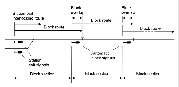
Station exit onto a
centralised block line
It is widely known that German mechanical signal boxes are based on double-wire interlocking. The only German region where rod transmission was quite popular in the pre-war era are the Palatines. However, double-wire interlocking is not the most essential difference from lever frames of the Anglo-Saxon world. The biggest difference is the locking frame that works by a completely different locking principle. Cascade locking which is the basis of all Anglo-Saxon frames has never been used in Germany. All German frames are based on route-related locking. In such a locking frame, each point lever moves a locking bar in the frame but there is no direct locking between point levers. As long no route is set up, all point levers can freely be operated in any desired sequence. Each route has a route locking bar running through the entire locking frame crosswise to the locking bars of the point and signal levers. The route locking bars are moved by small route levers arranged in a separate small lever frame. The route lever can only be moved if all point levers are in the required position for that route. Operating the route lever locks all point levers of that route at once and releases the signal lever. Pulling the signal lever locks the route lever so it cannot be restored. However, before the signal lever can be pulled, the route lever must be electrically locked by operating a route locking block instrument which is explained later. The picture below shows the typical interior of a German mechanical signal box. The interlocking machine is of the German standard type which was standardised in 1924.
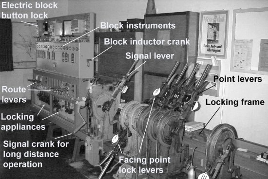
Interior
of a German mechanical signal box
The route levers are the small levers below the row of block instruments. Only a few of these block instruments belong to the manual line block system. There are also block instruments for electric route locking and block instruments of the so-called station block system. The station block system is not a block system in the common sense but part of the interlocking. It is explained later in an own chapter. Thus, most of the block instruments shown in the picture do not perform block functions but interlocking functions. Below the route levers, behind a glass window, are locking appliances that perform locking connections between block instruments, route levers, and signal levers.
One may ask why the route locking bars are not directly moved by the signal levers so that route levers were not needed. Having the route levers separated from signal levers has several reasons. One is that by having route levers that make all route-relevant distinctions, one signal lever can be used for a number of diverging routes starting at the same signal. Since a route lever is much smaller than a signal lever and can be used for two different routes, this will save a lot of space on the lever frame. A second reason for having route levers is the station block system which requires to lock routes without pulling a signal lever. However, in later developed power frames, route levers were combined with signal levers to so-called route-signal levers. A route-signal lever will lock the route and clear the signal with a single movement. Since a route-signal lever can also be used for two different routes, it will still save space on the lever frame.
A route lever has three positions. The normal position is the middle position in which the lever does not lock any route. From the middle position, the route lever can be moved to an up and a down position, each position corresponding to a specific route. Since a route lever moves just one route locking bar in the locking frame, one route locking bar has also three positions (left, middle, right) and is used for two different routes. Thus, the number of route locking bars equals the number of routes divided by two. Compared with the extremely complex locking frames that use cascade locking, locking frames of the route-related locking type are quite small and easy to understand. What makes German mechanical interlocking complicate and difficult to understand is not at all the locking frame but the station block system, obviously the most strange part for the Anglo-Saxon reader.
On German railways, all points are equipped with a point locking mechanism that is actuated by the same device that moves the points. A typical device is the clamp lock mechanism which is also known outside Germany. In mechanical interlocking, for passenger movements and freight movements at higher speeds, facing points are locked by an additional facing point lock operated by a separate lever. Because of the principle of double-wire interlocking, one facing point lock lever can lock several points. This reduces the number of facing point lock levers on the frame. In some older leverframes, facing point locks are even moved by the double wire that operates the signal. In those frames, facing point lock levers are obsolete.
A route is mechanically locked by the route lever which cannot be restored as long the signal lever is pulled. However, this is not yet a sufficient locking since there is no approach locking and, after the signal has been reset to stop, the route lever could be restored even if the train has not yet entirely cleared the points. For this reason, German law requires an enforced route locking (in German called "Fahrstraßenfestlegung"). In mechanical interlockings, the enforced route locking is effected by a route locking block instrument (German term: Fahrstraßenfestlegefeld, abbrivation: Ff). This is a DC block instrument that has no connected instrument but is connected to a short track circuit of the same type as used for block button release in the manual line block system. That track circuit is located at the route release point the train must have passed to release the route. Operating the route locking block instrument locks the route lever in the route locking position and releases the signal lever to clear the signal. After the signal has been restored to stop position, the route locking block instrument holds the route lever in the route locking position until the train has passed the track circuit at the route release point. There is no need to have separate route locking block instruments for every single route. The number of route locking instruments in a signal box depends on the number of routes that can be set up at the same time. The correct block instrument is selected by the position of the route levers.
The principle of enforced route locking is even more restrictive than the principle of approach locking which is used in many other countries. In some way, enforced route locking means that a route has to be approach locked before the signal can be cleared, regardless of the location of an approaching train. Once a signal has been cleared, it is no longer possible to cancel the route without activating a special safety procedure. To cancel a route, after having restored the signal, the operator has to break a seal at the route locking block instrument. The seal can only be replaced by a signal maintainer. However, there is no time lock. As long a seal is broken, special safety precautions are required for train movements. The handling of the seals is strongly watched by supervisory staff. Although developed for mechanical interlocking, the principle of enforced route locking survived all later developed generations of German interlocking systems and can still be found in the latest electronic control systems. Only the physical seals are now replaced by a special command procedure that is automatically registered.
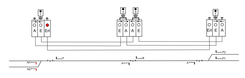
The following example shows the arrangement of block instruments and route levers of a small signal box that controls a junction of a double track line and a converging single track line outside station home signal limits. There are just four routes:
| Abbr. | Description |
|---|---|
| a/Rh | From signal A to R-heim | a/Ms | From signal A to M-stadt | b | From signal B to L-dorf |
| c | From signal C to L-dorf |
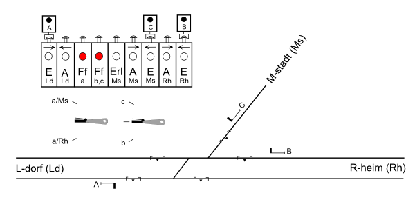
Junction interlocking
arrangement
Since two routes can be set up at the same time (a/Rh + b, a/Rh + c), two route locking block instruments are required, one for routes starting at signal A, and another for routes starting at signals B and C. In normal state, a route locking block instrument shows a red indicator since it must be operated to release a signal. Within each route, there are two short track circuits. The first is for block button release, and the second is for route release. The track circuit behind signal C performs two functions. For train coming from M-stadt, it is used for block button release, and for trains going to M-Stadt, it is used for route release.
In the following figures, route levers locked by block instruments are marked by red colour of the lever handle. In the next picture, signal A is cleared for an approaching train to R-heim. The left route lever is locked by the route locking block instrument (Ff instrument a) in the position for route a/Rh.
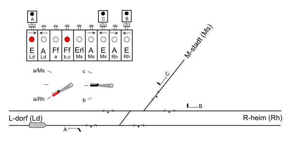
Route locked and signal
cleared
After the train has passed over the first track circuit and has released the block button, the signal is restored to stop position, the entrance instrument of the block section to R-heim is blocked, and the block section from L-dorf is released. The route locking block instrument keeps the route locked.
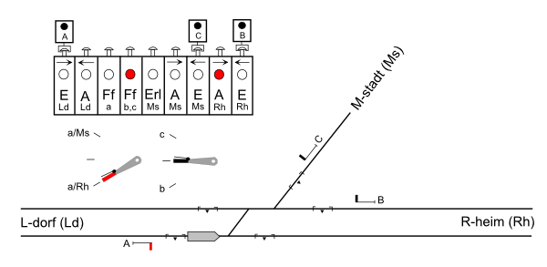
Signal restored, route kept
locked
After the train has passed over the second track circuit, the route locking block instrument is released. The route lever is no longer locked and can be restored to normal position.
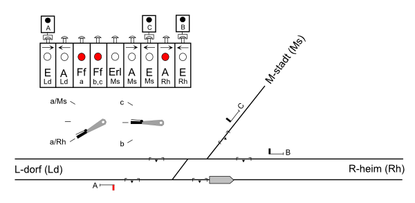
Route released
The station block system (German: Bahnhofsblock, Stationsblock) is not a block system in the sense of safe train separation but part of the interlocking system in all stations controlled by more than one signal box. Due to a maximum train length of 750 m for freight trains, this is the case in most stations with mechanical interlocking. The station block system performs the following functions:
The first point serves a similar purpose as slot controlled signals in British signal boxes. However, in German interlocking systems, interlocking between signal boxes is much more widely used. This is the reason why in big German station areas controlled by traditional signalling, you will never see such densily spaced signal bridges and gantries as typical for British terminals. The second point has no equivalent in the Anglo-Saxon world but is a very essential element in the German operating philosophy.
The principle of station block working is best to explain at a very simple example. But before, it is necessary to explain the block instruments used for station interlocking. All these block instruments are of the AC type.
| Abbr. | German term | Translation | Description |
|---|---|---|---|
| Ba | Befehlsabgabefeld | Command sending instrument | Operation of this instrument locks a route lever in the command box and releases a route lever in a dependent box. It is connected to a command receiving instrument in a dependent box. |
| Be | Befehlsempfangsfeld | Command receiving instrument | Holds a route lever in a dependent box locked in normal position until a command is received from the command box. Operation of this instrument returns the command after a train movement. It is connected to a command sending instrument in the command box. |
| Za | Zustimmungsabgabefeld | Confirmation sending instrument | Operation of this instrument locks a route lever in the dependent box and releases a route lever in the command box. It is connected to a confirmation receiving instrument in the command box. |
| Ze | Zustimmungsempfangsfeld | Confirmation receiving instrument | Holds a route lever in the command box locked in normal position until a route locking confirmation is received from a dependent box. Operation of this instrument returns the confirmation after a train movement. It is connected to a confirmation sending instrument in a dependent box. |
In normal state, command and confimation receiving instruments are blocked, and command and confimation sending instruments are unblocked. Since command and confirmation sending instruments are operated to release a signal in another signal box, all station block instruments show a red indicator in normal state.
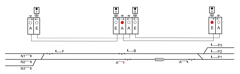
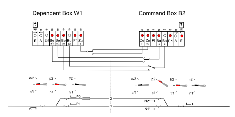
The most simple example to explain station block working is a crossing station on a single track line with one loop track and just two pairs of points controlled by two signal boxes. In the picture, the right signal box B2 is the command box staffed by the train director of the station, and the left signal box W1 is a dependent box staffed by a point operator. In this station there are the following interlocking routes:
| Abbr. | Description |
|---|---|
| a/1 | Entrance route from signal A to track 1 | a/2 | Entrance route from signal A to track 2 | p1 | Exit route from signal P1 |
| p2 | Exit route from signal P2 |
| f/1 | Entrance route from signal F to track 1 | f/2 | Entrance route from signal F to track 2 | n1 | Exit route from signal N1 |
| n2 | Exit route from signal N2 |
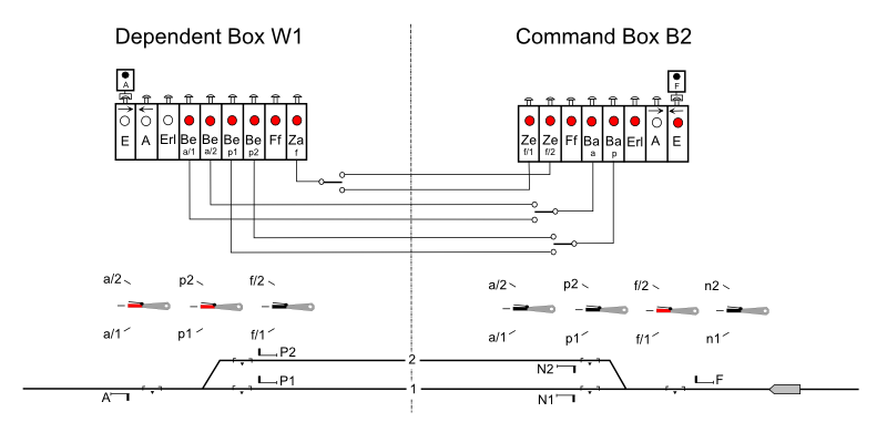
Station block
arrangement of a small crossing station
The command box has route levers for all routes of the station. The dependent box has only route levers for the routes where the dependent box is involved. In the dependent box, the route levers for the routes a/1, a/2, p1, and p2 are locked in normal position by command receiving instruments to hold the signals of these routes under control of the command box. The route lever for the routes f/1 and f/2 is not locked since the dependent box does not operate the signals for these routes. In the command box, only the route lever for the routes f/1 and f/2 is locked in normal position. Since these routes lead into the district of the dependent box, the train director has to receive a route locking confirmation from the dependent box before signal F can be cleared. To save block instruments, a command or confirmation sending instrument may be connected to several command or confirmation receiving instruments. In such a case, selector switches in the block line operated by the route levers select the block instruments needed for the specific route.
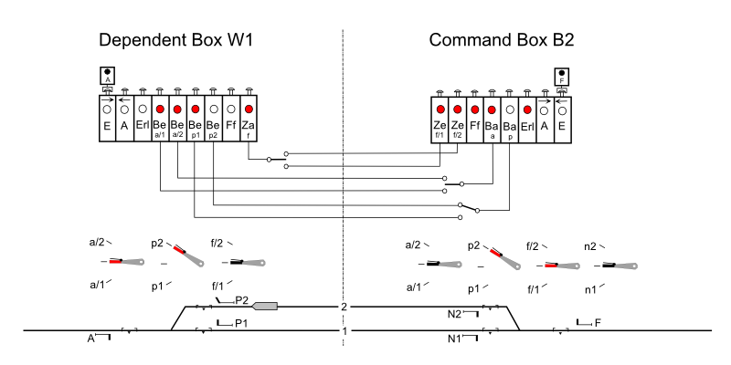
In the example, signal F should be cleared for an approaching train to enter track 2. To clear signal F, the train director has to require route locking confirmation for the route f/2 from the dependent box since that route leads into the control district of signal box W1. This is done via telephone or by bell code. After having set the points, the point operator moves the route lever in the locking position for route f/2 and operates the confirmation sending instrument. Now the router lever is electrically locked and can no longer be restored. The selector switch has connected the confirmation sending instrument to the confirmation receiving instrument for the route f/2 in the command box. Unblocking the confirmation receiving instrument releases the route lever to be moved for route f/2.
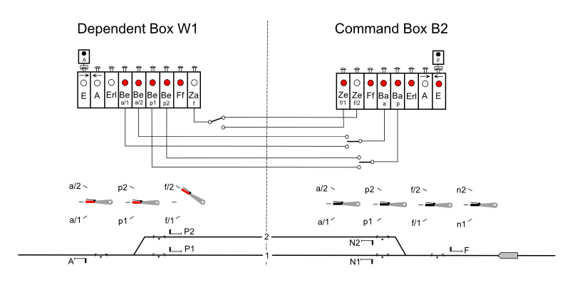
Route locking
confirmation received
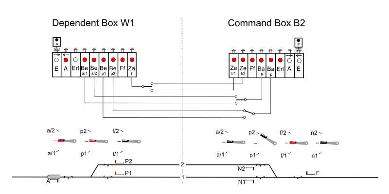
The train director can now move the route lever into the locking position for route f/2, operate the route locking instrument, and clear the signal.
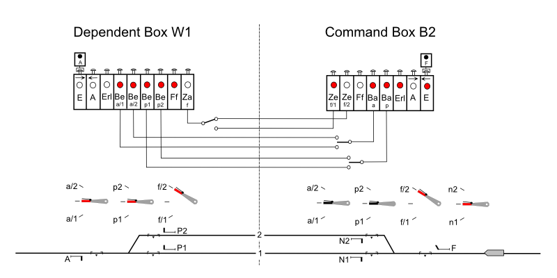
Home signal
cleared
Now, the home signal has been reset to stop, and the block section has been released. After the train has passed over the track circuit for route release, the route locking block instrument is released. The train director can now restore the route lever and return the confirmation to the dependent box by operating the confirmation receiving instrument. This unlocks the route lever in the dependent box. However, before restoring it, the point operator has to check that the train has come to a stop. This is required since the route lever could lock points in the overlap beyond the exit signal.
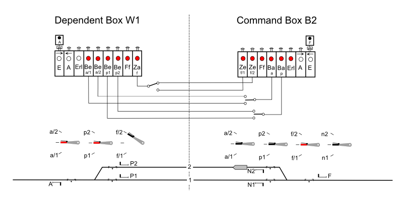
Route released, route
locking confirmation returned
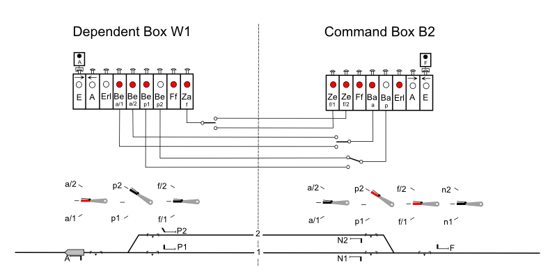
The train is now going to leave the station. The exit route of signal P2 is completely in the control area of signal box W1. However, since the point operator clears the signal, a command from the train director is required. The train director moves the route lever to the position for route p2 and operates the command sending instrument. This route lever does not lock any points in the command box. It just moves the selector switch in the block line, and it locks all conflicting routes in the locking frame. Thus, the train director is protected from sending commands for conflicting routes. In the dependent box, the received command releases the route lever to be moved into the locking position for route p2.
Command for exit route
received
The point operator can now move the route lever, operate the route locking block instrument, and clear the signal.
Exit signal cleared
The train has passed the track circuit for route release and has unblocked the route locking block instrument. Since the signal is still in the clear position, the point operator has to restore the signal lever first before the route lever can be restored.
Route locking block
instrument unblocked
After having the route lever restored, the received command can be returned to the command box. The route lever in the dependent box is now locked again, and the route lever in the command box is released to be restored to normal position.
Route released, command
returned
A received command or route locking confirmation must always only be used for one train movement. Between two trains following on the same route, all received commands and route locking confirmations for that route must be returned and received again. The reason is that a received command or route locking confirmation may confirm safety conditions that are not guarantied by the interlocking system and must be checked by the operator for every single train movement. The most important condition is track clear detection. In German mechanical interlocking, station tracks are usually not equipped with track circuits for line clear detection, not even berth circuits. Thus, track clear detection is visually checked by the operators. To prevent the operator from violating the rule to use a received command or route locking confirmation for just train, a so-called station rotation lock (German: Bahnhofswiederholungssperre) is used. After having restored a signal that depends from a command or a route confirmation, the rotation lock locks the signal lever until the command or confirmation has been returned.
The kind of station block working demonstrated here is the standard German station block working. There are several modifications of that system used on railways where the train director does not work on a signal box but has an office in the station building. In these systems, the train director has a pure command machine. To set up a route, the train director sends a route command to all signal boxes involved. After these signal boxes have electrically confirmed the route locking, a signal command is sent to the signal box that operates the signal lever. For that purpose, signal locking levers are used that can be released separately from the route levers. Generally, these systems are more complicate and more difficult to understand than the German standard station block system.
After having understood the station block working from this very simple example, one may imagine that in big terminal areas with hundreds of points and more than just two signal boxes, the station block design may become extremely complex. From a today's viewpoint, it seems a little strange that German railways developed such a complex system of electrical interlocking between signal boxes but never added track circuits for track clear detection on tracks controlled by mechanical interlocking.
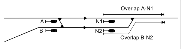
Overlaps are an essential element of the German safety philosophy. The point behind a signal that is protected by the overlap could be:
Points to be
protected by the overlap
The minimum overlap length depends on the kind of the signal, on the point to be protected, and on the maximum speed of a train approaching the signal. Here are the required minimum overlap lengths:
a) Beyond home signals and block signals
b) Beyond exit signals and intermediate interlocking signals
The overlap beyond home signals and block signals must not contain any points. The overlap beyond these signals is always kept clear. The overlap beyond exit signals and intermediate interlocking signals is only in effect as long a train is approaching the signal. Overlaps beyond exit signals and intermediate interlocking signals may contain points, which are interlocked with the signal in rear.
Typical overlap arrangement at a small station area
Facing points within the overlap are always locked as a route in approach to that signal is set up. Trailing points within the overlap are also locked but there is one exception. This exception are shared which are a German peculiarity. Shared overlaps means that overlaps of different routes set up at the same time may overlap each other.
Shared
overlaps
For this purpose, trailing points inside the overlap are unlocked. Due to ATP, which is required on all main lines in Germany, the probability of sliding past an exit signal or intermediate interlocking signal is quite low. Therefore, it is not regarded as being very probable that at the same place, two trains will run into their overlaps at the same time.
Swinging overlaps are not used on German railways. Facing points within the overlap are always locked. To provide some flexibility, selective overlaps are common in complex interlockings. Having selective overlaps means that, when lining up a route, the operator can make a choice between different possible overlaps. However, once a signal has been cleared, it is no longer possible to change the overlap.
Protective points are required by law in the following cases:
On junctions and crossovers of the open line, protective points are never used, regardless of line speed. A typical protective point arrangement on a high speed line looks like this:
Protective points on
a high speed line
On station tracks with a maximum speed not exceeding 160 km/h, the need for protective points depends on an individual evaluation of the local risk.
Even if protective points are not required, existing points that could provide flank protection are always used for that purpose. Therefore, the handling of selective protective points plays an important role in German interlocking.
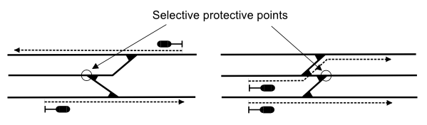
Selective
protective points
Those are protective points in a so-called "crotch layout". In such a layout, a track situated between two main tracks leads to facing points from where it is connected to both outer tracks. At a certain time, the points between the outer tracks can provide flank protection against movements on the middle track only to one of the outer tracks. This means, it is not possible to set up routes on both outer tracks at the same time, because these routes need the middle points to be locked in another position for the purpose of flank protection. When it is required to set up routes on both outer tracks at the same time, a decision must be made by the internal logic of the interlocking as to which one of the routes could be set up without flank protection. If this is not acceptable (e.g. because of frequent shunting on the middle track), additional protective points will be required.
In traditional German lever frames, protective points were permanently assigned to one of the two outer routes, usually to the route of higher priority. If possible, the other route gets remote flank protection. In relay and electronic interlocking, the control logic for selective protective points has become more complex. Two different principles are used:
Priority based setting is used if the two routes are of different priority. As long only one of the two routes is set up, this route will always get protection from the selective protective points. If the two routes are set up at the same time, the selective protective points will move into the protective position for the route of higher priority. The superior route will even take the protection away from the inferior route. The "First In - First Out" principle is used if the routes are of the same priority. If the two routes are set up at the same time, the route that was set up first will always get protection from the selective protective points. Both principles can be combined with an additional feature called "supplementary protective mode". That means, after the route for which flank protection was provided has released, the selective protective points will automatically switch to a protective position for the second route. This way, a maximum degree of flank protection is achieved.
On German railways, derailing devices must not be installed on main tracks. Derailing devices are only used to protect a main track against movements on a converging secondary track at places where protective points are not required. All derailing devices are of the block derail type. Trap points are not used on German railways.
